Wednesday, December 4, 2013

Exercise 4.9

This Exercise is Half Done, Please Ignore

To answer the following questions we will be using the simulator ProcSim

r1-r4 is mapped to temp registers t1-t4 respectively
r16 is mapped to s7

This is my sample asm code for running my simulation:

#init registers
.register $t1 1
.register $t2 2
.register $t3 3
.register $t4 4
.register $s7 200

main: sw $t4, -100($s7)
  slt $t1, $t2, $t3
exit:

4.9.1 What is the value of the instruction word?


a)
10101110111011001111111111111100
op           rs        rt         immediate
101011-10111-01100-1111111111111100
b)
00000001010010110100100000101010
op           rs        rt         rd         shamt  funct
000000-01010-01011-01001-00000-101010

4.9.2 What is the register number supplied to the register file’s “Read register 1” input? Is this register actually read? How about “Read register 2”?

a)10111
Also mentioned above in the machine code breakdown.


b)01010

4.9.3 What is the register number supplied to the register file’s “Write register” input? Is this register actually written?

a)01100
Also mentioned above in the machine code breakdown.


b)01001

Exercise 4.7


4.7.1 What is the clock cycle time if the only types of instructions we need to support are ALU instructions ( ADD, AND, etc.)?
a) 200+90+20+90+20 = 420ps
b) 750+300+50+250+50 = 1400ps

4.7.2 What is the clock cycle time if we only have to support LW instructions?
a) 200+90+20+90+250+20 = 670ps
b) 750+300+50+250+500+50 = 1900ps

4.7.3 What is the clock cycle time if we must support ADD, BEQ, LW, and SW instructions?

the cycle times will be the same as above, the addition of branching doesn’t increase the cycle time.  Implementation a: 15+10+70+20 = 115ps which is less than data memory latencies.
Implementation b is the same: 100+5+200+20 = 350ps

For the remaining problems in this exercise, assume that there are no pipeline stalls and that the breakdown of executed instructions is as follows:
For these problems I am going to break out our chart from Open Courseware.
4.7.4 In what fraction of all cycles is the data memory used?
Data memory is used in SW and LW as we are writings and reading to memory.
a) 25+10 = 35%
b) 30+20 = 50%
4.7.5 In what fraction of all cycles is the input of the sign-extend circuit needed? What is this circuit doing in cycles in which its input is not needed?
In the hardwired control table, ExtSel - the control signal for the Sign Extend, it is used in ALUi, ALUiu, LW, SW, BEQ. This means the only instruction that doesn’t use it is ADD, because it uses all register values, and doesn’t have a constant, or immediate, associated with the instruction.
a) 20%
b) 30%
A control signal is sent to the resource to activate its use or not, however, in the figure associated with these problems, that control signal does not exist, so we must assume the function performs no matter what.  However, in the case where it is not needed, even in its operations are performed, it is simply ignored because it isn’t used.

4.7.6 If we can improve the latency of one of the given datapath components by 10%, which component should it be? What is the speedup from this improvement?
There are two prime contenders here.  The first is Instruction memory, since it is used every cycle.  The second is Data Memory, since it has the longest latency.

We will assume 100 instructions
a)
I-Mem - 200ps - 100%
D-Mem - 250ps - 35%

200*.9 = 180 * 100 = 18000
250*.9 = 225 * 35 = 7875

200*100 = 20000 - 18000 = 2000ps change
250*35 = 8750 - 7875 = 875ps change

For a, the component to improve would be the Instruction memory.

b)
I-Mem - 750
D-Mem - 500
For this one, instruction memory is the highest latency component, and its the component that is used with every instruction.  Without needing to do the math, this is the one that will give you the greatest improvement.  However, here is the math anyway:

750*.9 = 675 * 100 = 67500
750-100 = 75000 - 67500 = 7500ps

Monday, December 2, 2013

Exercise 4.2


4.2.1 Which existing blocks (if any) can be used for this instruction?
a)  SEQ is a Boolean operation returning 1/true or 0/false if the two registers are equal.
reg, mux, alu
b) LWI leads the contents of a memory allocation that is the sum of two registry values.
reg, mux, alu, memory
Figure Below


4.2.2 Which  new  functional  blocks  (if  any)  do  we  need  for  this instruction?
a) a mux after ALU zero for Boolean 0 or 1
b) nothing
Figure Below


4.2.3 What new signals do we need (if any) from the control unit to support this instruction?
a) need control signal to operate new mux
b) nothing
Figure Below


 In the  following three problems, assume that we are starting with a datapath from Figure 
4.2, where I-Mem, Add, Mux, ALU, Regs, D-Mem, and Control blocks have latencies of 400ps, 100ps, 30ps, 120ps, 200ps, 350ps, and 100ps, respectively, and costs of 1000, 30, 10, 100, 200, 2000, and 500, respectively.
Costs
Instruction memory:1000
Registers:200
ALU:100
Data Memory:2000
Add:30*2 = 60
Mux:10*3 = 30
Control:500


Total Cost: 3890


4.2.4 What is the clock cycle time with and without this improvement?
Critical Path is PC->Instruction Mem->Registers->Mux->ALU->D-Mem->Mux
400+200+30+120+350+30 = 1130ps


a. ALU latency +300: 1130+300 = 1430ps
b. Control Latency+100 - matches registers for latency, so no change in critical path - 1130ps


4.2.5 What is the speedup achieved by adding this improvement?
a. While no direct speed up occurs in the critical path, and in fact, the cycle time is lengthened, since it adds MUL to the instruction set, 5% fewer instructions can be performed.
So, if we assume 1000 instructions at 1130ps, we have a run time of 1,130,000ps
Now with the improvement, we have 950 instructions at 1430 ps we have a run time of 1,358,500.


We have a performance decrease of 225800ps, instead of an increase.  The increase in cycle time is not recovered in the decrease in instruction count.


b.  The change does not affect cycle time, therefore no speedup is achieved.


4.2.6 Compare the cost/performance ratio with and without this improvement.
I will increase the instruction count to 1million.
Cost/Performance
Cost/(1/Execution Time)
1000000*1130 = 1130000000ps
.00113sec
3890/(1/.00113)) = 4.4


a. cost 3890+600 = 4490
1000000*.95*1430 = 1358500000ps
.0013585 sec
4490/(1/.0013585) = 6.1


b. cost 3890-400 = 3490
1000000*1130 = 1130000000ps
.00113sec
3490/(1/.00113) = 3.94


Improvement a, is not an improvement at all.  The increase in cycle time is never made up in the decrease in instruction count. When combined with the cost of the improvement, you have a system a fair amount worse than our baseline. To make this implementation and actual improvement, the usage of mul will need to be used much more frequently.


Improvement b is a true improvement.  With no sacrifice to cycle time, we have a reduced cost. Seems like an obvious improvement.

Thursday, November 21, 2013

Exercise 4.1

Exercise 4.1
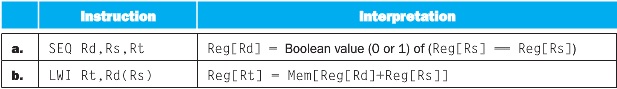
Different instructions utilize different hardware blocks in the basic single-cycle implementation. The next three problems in this exercise refer to the following instruction:

Instruction Interpretation
a. AND Rd,Rs,Rt
Reg[Rd] = Reg[Rs] AND Reg[Rt]
b. SW Rt,Offs(Rs)
Mem[Reg[Rs] + Offs] = Reg[Rt]
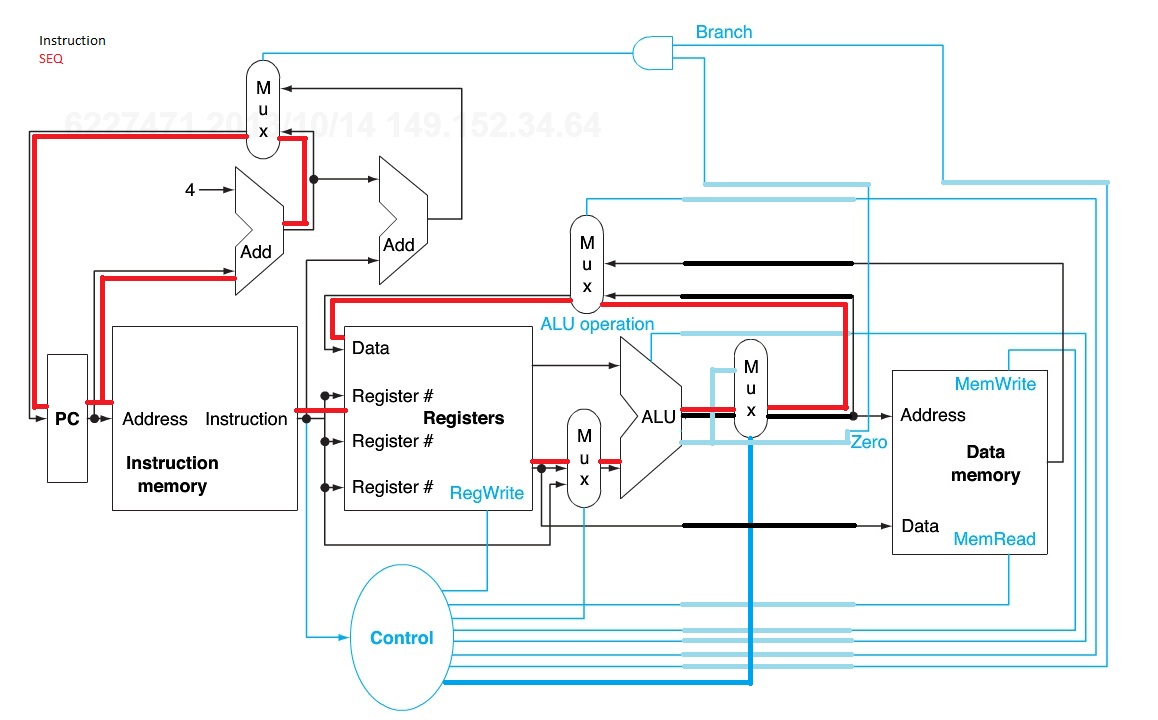
Figure 4.2


ExtSel is extend sign, which is not represented in our figure.
BSrc is the southern mux in the figure and is used to determine if an immediate operand or a register is passed to the ALU.
OpSel is ALU command
WBSel is middle mux, selecting whether the ALU output or a memory output is used as data.

4.1.1 What are the values of control signals generated by the control in Figure 4.2 for this instruction?
For these answers, i will be referencing the Control table above provided by MIT Open Courseware.
a) AND is an ALU Operation, so:
BSrc will look to register
OpSel will tell ALU to AND
MemW is false, we do not touch memory
RegW is true, we are writing back to register Rd
WBSrc is will set to use output from ALU as data
RegDst is Rd
PCSrc is PC + 4 since no jumps occur

b) SW is directly represented in our chart
BSrc will look to immediate operand Offs
OpSel will tell ALU to ADD the Offset to the Rs register
MemW is true, we are writing a register to memory
RegW is false, we are not writing back to a register
WBSrc is ignored
RegDst is ignored
PCSrc is PC + 4 since no jumps occur


4.1.2 Which  resources  (blocks)  perform  a  useful  function  for  this instruction?
a) pc, instruct mem, alu, mux, registers
    We are not using memory or jumping
b) pc, instruct mem, alu, mux, mem, reg

4.1.3 Which resources (blocks) produce outputs, but their outputs are not used for this instruction? Which resources produce no outputs for this instruction?
a) branch, data memory
b) branch

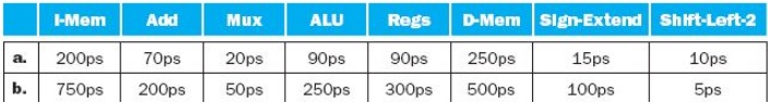
Different execution units and blocks of digital logic have different latencies (time needed to do their work). In Figure 4.2 there are seven kinds of major blocks. Latencies of blocks along the critical (longest-latency) path for an instruction determine the minimum latency of that instruction. For the remaining three problems in this exercise, assume the following resource latencies:

Since no mention is made as to analog or digital mux, I am assuming digital and that 20ps will always be spent.

I-Mem
Add
Mux
ALU
Regs
D-Mem
Control
a. 200ps
70ps
20ps
90ps
90ps
250ps
40ps
b. 750ps
200ps
50ps
250ps
300ps
500ps
300ps


4.1.4 What is the critical path for an MIPS AND instruction?
Figure above outlines latencies, and calculates Critical path to ALU completion.

The PC +4 and Control have lower latencies than other parts functioning in parallel. Control is slower the the registers, and data mem is not used.

a)instruction mem, reg, mux, alu, mux
400 + 20(writeback to reg mux) = 420ps
b) 1350+20=1370ps

4.1.5 What is the critical path for an MIPS load (LD) instruction?
Load will read from mem and write to register so we must use data memory and the mux to register data.
a)400+250+20 = 670ps
b)1350+500+50 = 1900ps

4.1.6 What is the critical path for an MIPS BEQ instruction?
beq will go up to the branch, and mux the new address from the ALU output to be the new Program Counter.
a)400+20 = 420ps
b)1350+50 = 1400ps


This Exercise focus’ on Critical Paths of Operations and the resources they use.
As such, we cover 4 distinct Control variations as described in the MIT Open Courseware Figures: ALU, SW, LW, BEQ.
To show all these in execution, I am running a simulation in ProcSim: http://jamesgart.com/procsim/
The resource configuration is slightly different from the one in the figure used above, however the operations performed are identical.
The Assembly I am executing is in the lower right of the images and the current register values is in the middle right.

Wednesday, November 20, 2013

Exercise 3.15

a. 1/3
b. 1/10

3.15.1 Write down the bit pattern in the mantissa assuming a
floating point format that uses binary numbers in the mantissa (essentially what
you have been doing in this chapter). Assume there are 24 bits, and you do not need
to normalize. Is this representation exact?
a) ⅓ can’t be represented since it repeats 3333 infinitely, and we are in base 2 therefore we must round up a little
010101010101010101010110

b) 1/10 also can’t be represented in base 2 and must be approximated.
000110011001100110011001

Work on Spreadsheet.

3.15.2 Write down the bit pattern in the mantissa assuming a
floating point format that uses Binary Coded Decimal (base 10) numbers in the
mantissa instead of base 2. Assume there are 24 bits, and you do not need to nor-
maize. Is this representation exact?

a)This also can’t be represented exactly
0011 = 3
.3      3       3      3     3      3
001100110011001100110011

b)This is our first number that CAN be represented exactly.
1/10 = .1
0001 = 1
.1     0       0      0      0       0
000100000000000000000000

3.15.3 Write down the bit pattern assuming that we are using
base 15 numbers in the mantissa instead of base 2. (Base 16 numbers use the sym-
bos 0–9 and A–F. Base 15 numbers would use 0–9 and A–E.) Assume there are 24
bits, and you do not need to normalize. Is this representation exact?

a)The first case in which ⅓ can in fact be represented exactly.
1/3 = 5/15
5 = 0101
5     0     0     0     0     0
010100000000000000000000

b)Can’t Be Represented Exactly
(1/10) = (x/15)
x = 1.5
Round(1.5) = 2
2 = 0010
0010 0010 0010 0010 0010 0010

3.15.4 Write down the bit pattern assuming that we are using
base 30 numbers in the mantissa instead of base 2. (Base 16 numbers use the sym-
bos 0–9 and A–F. Base 30 numbers would use 0–9 and A–T.) Assume there are 20
bits, and you do not need to normalize. Is this representation exact? Do you see any
advantage to using this approach?

a)⅓ = 10/30
10 = 01010
01010 00000 00000 00000

b) 1/10 = 3/30
3 = 00011
00011 00000 00000 00000


Using a larger base allows a greater flexibility when non normalized at the cost of precision.  Base 30 as represented above has 4 decimal digits, as opposed to base 10 above, which has 6.
This is mentioned here in a comparison with storing the value of the speed of light.  “floating-point numbers cannot represent point coordinates with atomic accuracy at galactic distances, only close to the origin” the smaller the number, the greater the precision we need.  The larger the number, the greater a exponent value we need.

I also created a Mips program to do parts of these calculations.


.data
Ask_base: .asciiz "\Please Enter a Base\n"
Ask_top: .asciiz "\Please Fraction Top\n"
Ask_bottem: .asciiz "\Please Fraction Bottem\n"
sig:  .asciiz "\Significand\n"
space:  .asciiz "\n"
not_possible: .asciiz "\This Fraction Cannot be accurately represented\n"
.text
main:
la $a0, Ask_base
li $v0, 4
syscall #print Ask_base
li $v0, 5
syscall
move $t0, $v0 #t0 is our base
la $a0, Ask_top
li $v0, 4
syscall #print Ask_top
li $v0, 5
syscall
move $t1, $v0 #t1 is top of fraction
la $a0, Ask_bottem
li $v0, 4
syscall #print Ask_bottem
li $v0, 5
syscall
move $t2, $v0 #t1 is bottem of fraction
#goal is to test first if its possible to represent
#if something can't be represented, it requires a fair amount of estimation
#this is outside the scope of this program
mulu $s0, $t0, $t1
divu $s0, $t2
mfhi $s1
mflo $s2
beqz $s1, calc  #if there is a remainer, we print and exit, else we continue
la $a0, not_possible
li $v0, 4
syscall #print not_possible
j done
calc: #not that there is much calc
la $a0, sig
li $v0, 4
syscall #significand
li $v0, 1 #print_int
move $a0, $s2
syscall
la $a0, space
li $v0, 4
syscall #print space

#************** Convert to Bit notation  *************************#
move $t2, $s0      # Move to temp
       li $s1, 24         # Set up a loop counter - assuming 24 bit
Loop:
       ror $t2, $t2, 1    # Roll the bits left by one bit - wraps highest bit to lowest bit (where we need it!)
       and $t0, $t2, 1    # Mask off lowest bit
       add $t0, $t0, 48   # Combine it with ASCII code for '0', becomes 0 or 1
      
       move $a0, $t0      # Output the ASCII character
       li $v0, 11
       syscall
      
       subi $s1, $s1, 1   # Decrement loop counter
       bne $s1, $zero, Loop  # Keep looping if loop counter is not zero
#I started to do this but I stopped here, it doesn't take into account the appropriate bit size. and the calculations themselves are slightly off
#example, a base 16 needs 4 bits, int 5 isn’t 1110 in binary
#I kept this in here as reference to the attempt
done:
#example
#input base 15
#input top 1
#input bottem 3
##output##
#Significand
#5
#111000000000000000000000